• Skip to primary navigation
  • Skip to main content
  • Skip to primary sidebar
  • Skip to footer

Microcontroller Tips

Microcontroller engineering resources, new microcontroller products and electronics engineering news

  • Products
    • 8-bit
    • 16-bit
    • 32-bit
    • 64-bit
  • Applications
    • Automotive
    • Connectivity
    • Consumer Electronics
    • Industrial
    • Medical
    • Security
  • EE Forums
    • EDABoard.com
    • Electro-Tech-Online.com
  • Videos
    • TI Microcontroller Videos
  • EE Resources
    • DesignFast
    • eBooks / Tech Tips
    • FAQs
    • LEAP Awards
    • Podcasts
    • Webinars
    • White Papers
  • EE Learning Center
    • Design Guides
      • WiFi & the IOT Design Guide
      • Microcontrollers Design Guide
      • State of the Art Inductors Design Guide
      • Power Electronics & Programmable Power

Protecting an MCU: Build your own optocoupler

January 21, 2019 By Scott Thornton

Microcontrollers are widely used for controlling transistors and relays. Transistors and relays are used for actuating or (energizing) equipment with a higher voltage than an MCU can handle. For example, fans, lights, television, door locks, furnaces, and appliances can be automated using an MCU. However, most operate at higher voltages than the voltage tolerances designated in an MCU’s Input/Output (I/O) specification. Several board manufacturers use microcontrollers that usually operate in the range of 3 V DC to -5 V DC. When high voltage equipment is controlled by (and electrically connected to) an MCU, the high voltage equipment produces back EMF headed towards the MCU’s circuit and adds noise to the signals. These noisy signals can cause circuits to malfunction or cause permanent damage.

Another major challenge is protecting sensitive circuits from the risk of receiving electrical surges. High voltage equipment, powered by a high voltage source, can initiate an electrical surge. If a sensitive circuit is exposed to an electrical surge, the components can burn up immediately. This means an electrical surge can “let out the magic smoke in engineering slang.”

To reject back EMF, noise, and electrical surges from entering an MCU circuit, optocouplers are often used. Optocouplers create a safe connection between high voltage equipment and microcontrollers with complete electrical insulation. Suppose the high voltage circuit induces an electrical surge. In that case, the surge remains only on the output side of the optocoupler, and the circuit at the input side remains safe and unaffected, as both sides are electrically isolated. Optocouplers are also called photodiodes, optoisolators, photocouplers, photo relays, and optical isolators.

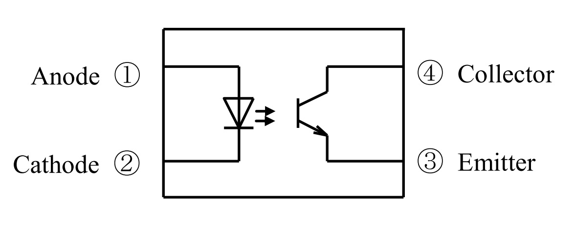
Internal view of a phototransistor-based optocoupler

Phototransistor-based optocouplers contain Infrared Emitting Diodes (IRED) on the input side and a phototransistor on the output side. Both sides are optically connected, and there is no electrical connection between the input and output sides. The IRED turns on when a voltage signal is passed on the input side. The light that the IRED emits then falls on the receiving phototransistor, resulting in current flow through the phototransistor’s collector and emitter.

Figure 1: Internal connection diagram of a phototransistor-based optocoupler consisting of an IRED at left and a phototransistor on the right. (Source: sharp-world.com)

How to make optocouplers at home

Although many optocouplers are relatively cheap and readily available online, they can be developed at home using an LED, a light-dependent resistor, and an opaque tube, perhaps made with duct tape.

Figure 2: Basic components for making an optocoupler at home. (Source: Author)

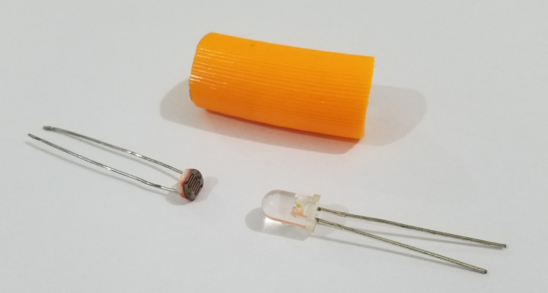
The phototransistor and LED are inserted inside the tube, facing each other. Tightly enclose the tube so that an external light source cannot affect the phototransistor. It is recommended to use an internally reflective tube, however, as a non-reflective tube might absorb LED light, affecting the efficiency of the optocoupler. This simple design can be used in hobby projects, functioning quite well as a standard optocoupler.


References
http://www.cel.com/pdf/appnotes/an3020.pdf
https://www.autodesk.com/products/eagle/blog/how-an-optocoupler-works/


Filed Under: FAQ, Featured, microcontroller Tagged With: basics, FAQ

Primary Sidebar

DesignFast

Design Fast Logo
Component Selection Made Simple.

Try it Today
design fast globle

EE Training Center Classrooms

EE Classrooms

CURRENT DIGITAL ISSUE

A frequency you can count on There are few constants in life, but what few there are might include death, taxes, and a U.S. grid frequency that doesn’t vary by more than ±0.5 Hz. However, the certainty of the grid frequency is coming into question, thanks to the rising percentage of renewable energy sources that…

Digital Edition Back Issues

Subscribe to our Newsletter

Subscribe to weekly industry news, new product innovations and more.

Subscribe today

RSS Current EDABoard.com discussions

  • How to set USB port as RS-485 entrance? How to interpret Growatt solar inverter commands?
  • Find Critical Path in Cadence Genus?
  • Simulation of a Press-ON-Press-OFF push button
  • HFSS 2022 R2 - Waveguide port configuration
  • Why this antenna azimuth and elevation direction are the same?

RSS Current Electro-Tech-Online.com Discussions

  • How know if solder iron has good quality tip?
  • How does a transistor works as a switch?
  • Peltier control
  • How to set USB port as RS-485 entrance? How to interpret Growatt solar inverter commands?
  • Component Identification

Footer

Microcontroller Tips

EE World Online Network

  • DesignFast
  • EE World Online
  • EDA Board Forums
  • Electro Tech Online Forums
  • Connector Tips
  • Analog IC Tips
  • Power Electronic Tips
  • Sensor Tips
  • Test and Measurement Tips
  • Wire and Cable Tips
  • 5G Technology World

Microcontroller Tips

  • Subscribe to our newsletter
  • Advertise with us
  • Contact us
  • About us
Follow us on Twitter Add us on Facebook Follow us on YouTube  Follow us on Instagram

Copyright © 2022 · WTWH Media LLC and its licensors. All rights reserved.
The material on this site may not be reproduced, distributed, transmitted, cached or otherwise used, except with the prior written permission of WTWH Media.

Privacy Policy