Electrically driven reaction wheels use conservation of angular momentum to keep a satellite pointed in the right direction, eliminating the need for fuel-powered and limited thrusters.
Part 1 was an introduction to reaction wheel basics. This part continues the investigation into their performance and construction.
Physics and analysis
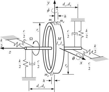
Although the basic principle of reaction wheels is relatively simple, it’s no surprise that a fully functioning precision unit includes much more than just controlling a spinning rotor. As with the gyroscope, error and imperfection sources include friction, damping, flexing, and other factors. Detailed models using these real-world factors are needed to fully analyze error sources and their magnitude (Figure 1). This is especially the situation as the reaction wheel usually functions in closed-loop, autonomous system design, and in-use “calibration” or fine-tuning is both impractical and undesirable.
Make or buy
Reaction wheels are used in nearly all orbiting space vehicles. For example, the Hubble space telescope was launched with six for redundancy. Over its long life, four of them have been replaced by Space Shuttle astronauts, as they failed due to wear-out beyond their service life. (Those failures actually gave scientists a good opportunity to study long-term lubricant performance in the vacuum of space on the returned units.)
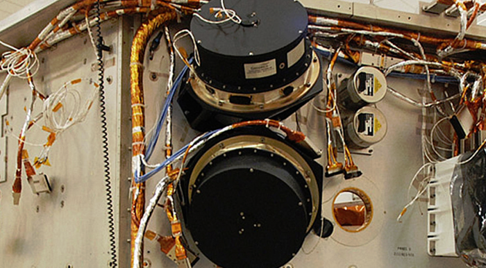
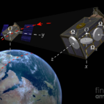
The Kepler space telescope was launched in 2009, and in 2012, one of its four reaction wheels failed (Figure 2). Since it required only three reaction wheels to aim the telescope accurately, its mission continued, but a second reaction wheel failed in 2013, this ending Kepler’s primary mission. Despite this loss, its primary mission goal was re-directed, and a clever “hack” was used to keep Kepler viable until its official retirement in 2018 (more on this later).
Of course, the recently launched James Webb Space Telescope (JWST) has multiple primary and backup reaction wheels to maintain its attitude. These are built by Rockwell Collins Deutschland GBMH (Formerly Teldix) and are descendants of the Teldix reaction wheels used on NASA’s Chandra, EOS Aqua, and Aura Missions.
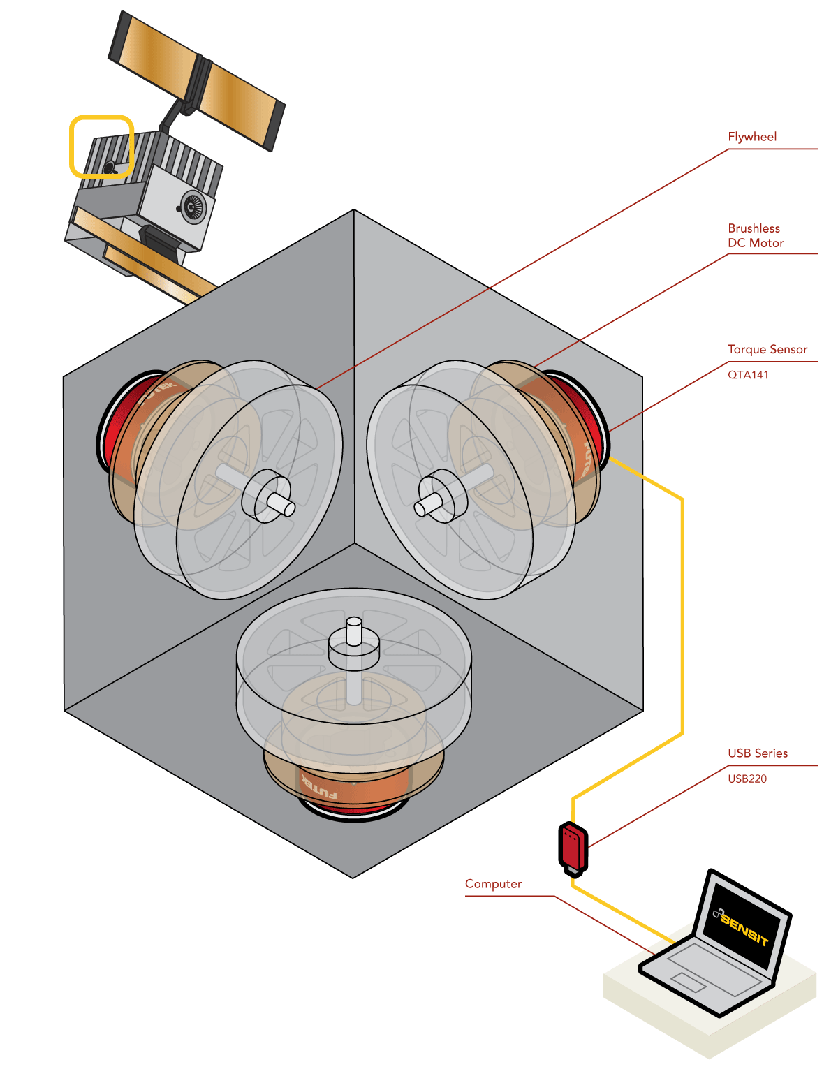
However, reaction wheels are not limited to large or one-of-a-kind satellites. Due to their fairly simple construction (“simple” only in the relative sense), small versions are also used in the very popular CubeSats; some of these are tested and controlled via a PC and USB interface (Figure 3).
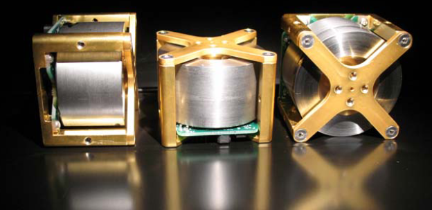
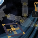
Another example is discussed in a PowerPoint presentation from the University of Toronto Space Flight Laboratory (UTSFL) (see External Reference 1). This presentation illuminates some of the design insights and tradeoffs explored as their team had about one year to design and build a modest run of 15 reaction-wheel units for their CanX satellite program (Figure 4). These include issues related to the use of standard versus custom electric motors, magnetic design, enclosure, bearings, and final achieved performance specifications; in the end, they built 20 units on schedule.
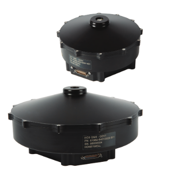
Standard “off the shelf” commercial reaction-wheel units are available for small to medium satellites from vendors such as Honeywell Aerospace, among others. Their 7-inch diameter HC7 and 9-inch HC9 are complete, enclosed reaction wheel assemblies (RWAs) offering 6 and 11.5 newton-meter-seconds of momentum, respectively; these units are complete with integral electronics and have a single RS-422 connector for signals and power (Figure 5).
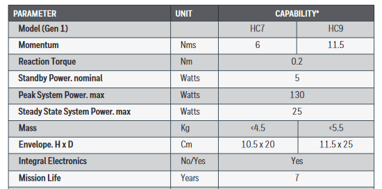
A look at their top-level specifications shows other key parameters such as power requirements, mass, size, and anticipated operational life (Figure 6).
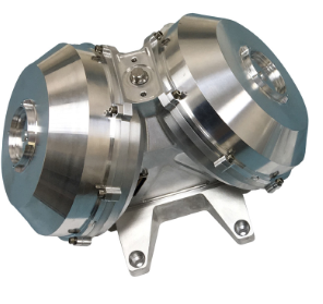
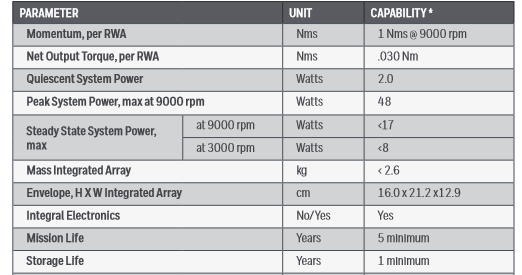
For those situations where the designers prefer to provide their own electronics, the Honeywell HR04 reaction-wheel core is also available (Figure 7); again, the top-tier specifications are revealing (Figure 8).
Whether for an LEO such as a CubeSat, an MEO satellite, or even a geostationary one, the reaction-wheel design and operation life match the satellite’s expected operational life. Keep in mind that an LEO has a life of about a year before its orbit decays, an MEO may have several years, and a geostationary satellite life would be on the order of a decade. A unit designed for a longer life than needed would be more costly, heavier, more complicated, and harder to evaluate for long-term performance – in other words, overdesigned at a cost in time, money, intricacies, and mass.
Make your own at home?
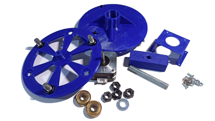
Some advanced experimenters even build their own reaction wheels simply for the experience and experience of doing so. One amazing example is described in Reference 2 from Charles’ Lab in France (don’t worry, the English is perfect!). It shows the full electronic and mechanical design, construction, evaluation, and more, including parts fabricated via 3-D printing after CAD modeling (Figure 9).
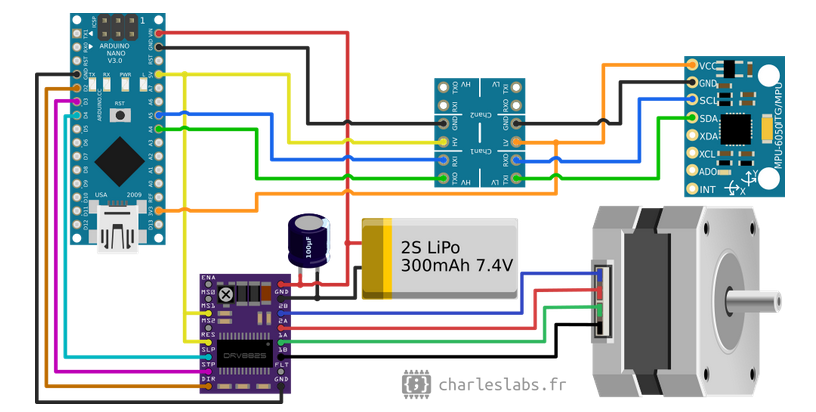
The electronics of this “homemade” reaction wheel has three primary functions:
- Measure the current angular speed via the MPU6050 gyroscope/accelerometer MEMS chip,
- Drive the stepper motor using a DRV8825 module,
- Run the control algorithms on ATmega328 microcontroller, on an Arduino Nano board.
Their roles are detailed in the electronics wiring diagram (Figure 10):
Issues and alternatives
Reaction wheels are widely used, but, as with all solutions, they have some shortcomings and can degrade or fail. In addition to these, they can “suffer” from a condition called “saturation.” If there is a small continuous torque on a satellite (which may be from solar radiation pressure), the reaction wheels spin continuously, faster and faster, to counteract it.
There needs to be a way to “dump” the momentum, analogous to deliberately discharging a capacitor to counteract this. The usual technique, used by the Hubble Space Telescope and other satellites, is to use a set of electromagnets (again, the virtues of electrically powered functions) in a “magnetorquer” to exert a weak countering torque against the Earth’s magnetic field as the satellite “cuts through” that extended field.
The countertorque generated by this technique is a function of magnetorquer’s size and power, of course, as well as the satellite’s altitude, as the Earth’s magnetic field drops off rapidly with distance. There are even cases where a reaction wheel has failed, so the magnetorquer alone was being used to aid in attitude adjustment and control, although it is not as effective or efficient as the reaction wheel – it has been done.
Similarly, the radiation pressure, which is partially responsible for the changes in satellite attitude, can also be leveraged to counteract some problems. By adjusting the orientation of the vanes on the satellite, the radiation pressure can be managed and employed beneficially to some extent; this is somewhat analogous to tacking a sailboat against the wind, although there is a “cost” in power usage and accuracy. But sometimes difficult times call for difficult solutions: this technique was used on the Kepler space telescope to maintain attitude for its refined mission after two of its four wheels failed.
Conclusion
Reaction-wheel systems show how basic physics principles can offer creative solutions to challenging problems. At the same time, taking these ideas and making them into practical, effective, high-performance solutions requires detailed analysis, modeling, and simulation, all followed by careful consideration of the operating environment, materials, electronics, fabrication, and installation.
Related EE World Content
How to make the most of low-cost satellites for remote IoT apps
Enhanced GNSS constellation simulator helps field satellite navigation systems
Smaller, cheaper, better: Microsatellites
Challenges in designing electronics for satellites
Gyroscopes, Part 1: Context and mechanical designs
Now that’s a test instrument: Inside the Webb space telescope
External References
- University of Toronto Space Flight Laboratory, “Enabling Reaction Wheel Technology for High
Performance Nanosatellite Attitude Control” - Charles’ Labs, “Reaction Wheel Attitude Control”
- Universe Today, “Spacecraft Gyroscopes And Reaction Wheels. You Can Never Have Enough”
- Space News, “Kepler Space Telescope Reaction Wheel Remains a Concern”
- Futek Advanced Sensor Technology, “Torque Sensor – Satellite Reaction Wheel Torque”
- Science Direct, “Micro-vibration model and parameter estimation method of a reaction wheel assembly”
- Honeywell Aerospace, “Small Satellite Class Reaction Wheel Assembly (RWA) HC7 AND HC9”
- Honeywell Aerospace, “Small Satellite Class Reaction Wheel Assembly (RWA) HRO4”
- Astrobytes, “Kepler Reaction Wheel Failure Cripples Spacecraft, but Mission Thrives”
- Tech Briefs, “Ultra-High-Speed Magnetically Levitated Reaction Wheels for Small Satellites”
- Utah State University, “Design and Testing of a Nanosatellite Simulator Reaction Wheel Attitude Control System”
- Wikipedia, “Reaction Wheel”
- Science Direct, “Optimal uses of reaction wheels in the pyramid configuration using a new minimum infinity-norm solution”


Dear Sir,
After setting the satellite direction, What would be doing for rotated flywheel.
How can you decrease and stop its rotation?
Regrads
Mahdi