We cut one of these balls apart so you needn’t destroy yours to get a look at its internals.
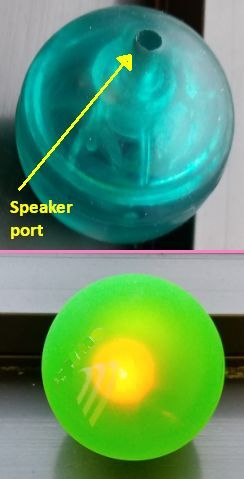
If you’ve ever attended a trade show, you might have seen a booth give-away item that consisted of a see-through bouncing ball with a flashing LED or two inside and sometimes a noise maker.
When you slice open one of these balls, you find the electronics sit in a clear plastic egg-shell-like enclosure that pops apart when the rubbery outer ball is cut away. There isn’t much to the electronics. There is a single IC controlling the LEDs. It is hidden under a little black bulge that is actually a protective epoxy coating. The chip mounts to the circuit board by a technique called “Chip on Board,” a mounting technique often found in inexpensive consumer electronics. If you could look beneath the epoxy, you’d see a chip die directly mounted on the PCB with the bond wires connected to copper traces.
That’s really about all we can say about the chip. If we pry off the epoxy, we destroy the chip in the process. And looking at the die itself won’t tell us much about how it works unless we bring in a scanning electron microscope. That’s a multimillion-dollar instrument, and we don’t quite have the budget for it.
What’s also noteworthy is what’s NOT on the circuit board. There are no passive components – no resistors, no inductors, no capacitors — at least on the version that doesn’t contain a noise maker. Everything happens on the IC.
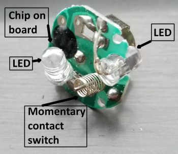
That’s what you might expect in a piece of electronics that’s cheap enough to be a giveaway item. But the chip running the show isn’t the most interesting part of the ball. The more intriguing aspect of it is how the LEDs get actuated when you bounce the ball. That happens courtesy of a super-simple mechanical switch consisting of a spring and a metal pin.
The pin sits in the center of the spring and is oriented along the spring’s vertical axis so that when the spring bends over far enough, the spring and the pin touch. The spring bends or deflects outside its axis when the ball bounces with sufficient force to move it. When the pin touches the spring, the momentary contact causes the IC to flash the LEDs for a period of time.
From looking at the orientation of the spring and pin, it also becomes clear why these balls sometimes bounce without actuating their LEDs. If the ball bounces so the pin is perpendicular to the bounce direction, the spring just moves up and down in its axis and doesn’t deflect to touch the pin.
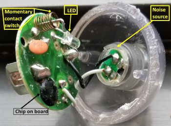
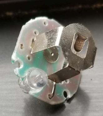
Some of these balls contain a little noisemaker as well as LEDs. The only difference in the electronics between the two versions is an additional capacitor as well as the noise maker. The only other component in the ball is a battery holder which holds two silver-oxide 1.5-v button cells.
Both the balls and those that also contain the noise maker use the same two button cells, so the noise-maker versions run out of juice a bit quicker because they have to power both the LEDs and the noise maker. And when the ball runs out of juice you will be left with a bouncing ball of the non-lighting, non-noise-making variety.
With that, we’ve kept our eye on this particular ball long enough.


Any idea where I can read more about chip dies. I shaved off the epoxy until I got to the traces, and didn’t see any chip?
i need these balls in huge numbers anyone knows this name please help me
Dollar Tree stores in Lexington, KY are selling them sometimes – in Dec 2020 and early Jan 2021 I purchased some – I was in different stores and over 4 week period I bought a total of 14 for a $1.00 each – I have to bounced them to find ones that lighted up.
Amusing toy to owen. Hard to find now. You could contact them on their website. Good luck’
The battery holder has detached from the circuit board. I wasn’t going to spend too much time fixing it but I would be interested to know how to reattach the two pronged battery holder to the circuit board. Always interested in understanding how things function.
Any reason why the ball would light up randomly without being touched bounced moved or anything. I have one that must be defective it is in a basket of other similar balls for my toddler. While sitting quietly in the room, no jumping or big trucks driving by causing vibration, it randomly lights up. Could the spring/pin be bent or something?