Antennas are a critical part of the link budget in all wireless communications applications, including Wi-Fi. In addition to the numerous antenna performance and link budget issues in wireless communications, there are general architectural challenges. The architectural options are the focus of this FAQ, including; long-distance versus local Wi-Fi and the use of directional vs. omnidirectional antennas, the selection of antennas for multipath environments, how the use of multiple antennas can improve Wi-Fi router performance, and the evolution and use of beamforming in Wi-Fi.
Wi-Fi is generally considered a short-distance wireless communication technology used to build local networks. But with the right antenna, Wi-Fi signals can reach 15 kilometers (km) (over 9 miles). Wi-Fi signals can travel through thin walls or isolated vegetation but not through large buildings or stands of trees. In addition, to signal loss due to obstructions, the transmission can suffer from losses of data packets and reduced signal strength as the distance increases. There are three general requirements when sending Wi-Fi signals over long distances:
- A direct line of sight connection is needed with no obstacles between the sending and receiving antennas.
- It’s generally preferable for the sending and receiving antennas to be on the same, or nearly the same, horizontal plane.
- Directional antennas need to be used on the sending and receiving sides of the transmission. Antennas with a smaller aperture angle require more accurate orientation but can transmit over longer distances.
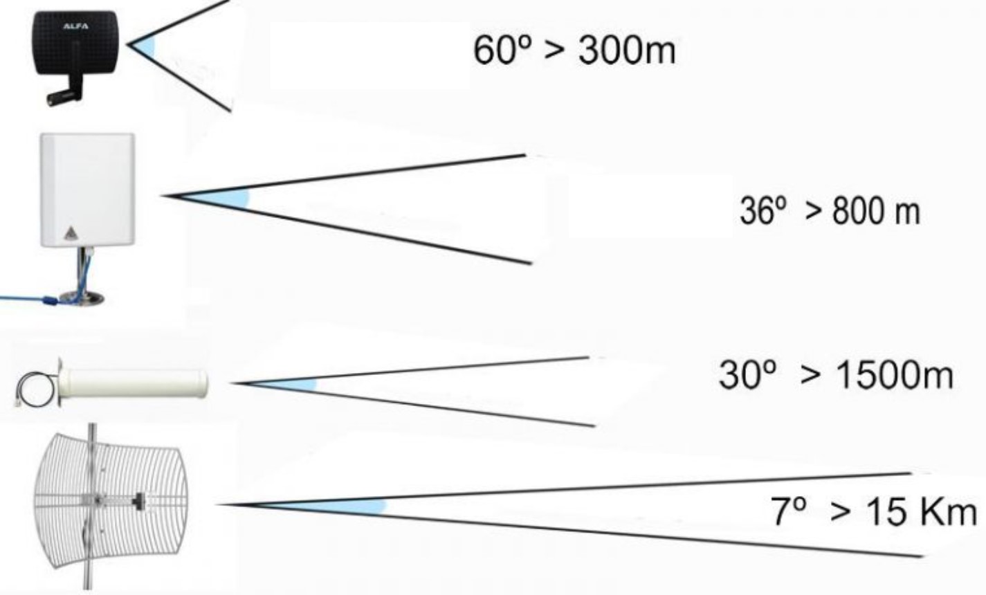
There are several antenna choices for long-distance Wi-Fi with tradeoffs between aperture angles and transmission distances (Figure 1). Panel antennas are the easiest to use and don’t need precise alignment. A small panel antenna can reach over 300 meters since it has an open-angle. Larger panel antennas with smaller apertures can transmit 800 meters or more. Yagi and parabolic antennas have even smaller apertures and can transmit between 1 and 15 km, but they must be aligned as accurately as possible.
Antenna diversity in multipath environments
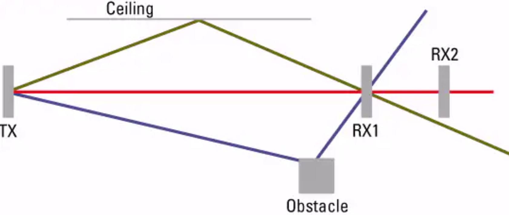
Antenna diversity generally refers to using two antennas for each radio, increasing the probability of one of the two receiving a better signal. The antennas must be separate but equal at each location. Diversity addresses challenges experienced by wireless networks in multipath environments. The antennas are physically separated from each other to ensure that each one encounters different multipath propagation effects. Signal null points are located throughout multipath environments. In some instances, it’s necessary to move antennas around to avoid those null points and enable adequate reception. Diversity is intended to maximize throughput by minimizing the number of dropped packets.
The transmission wavelength changes with the frequency and determines how an RF wave bounces, how far it travels and where the null(s) occur. A 5GHz wave has a length of about 6 cm (2.36 inches), while a 2.4 GHz wave has a length of about 12.5 cm (4.92 inches). Delay spread is a measure of multipath performance and is defined as the time between when the main signal arrives and when the last reflected signal arrives. The amount of delay is related to the environment and size of the network. For residences, it’s typically under 50 ns; in offices, it can be 100 ns, and in manufacturing and warehouse environments, it can be 300 ns or more (Figure 2).
A multipath signal can have good RF signal strength yet have poor signal quality. In a typical antenna diversity application, each access point samples the signals from the two transmitting antennas and uses the best combination of signal strength and quality. Antenna diversity is not meant to extend a Wi-Fi router’s coverage range or bandwidth but to enhance the coverage by eliminating multipath distortion and signal nulls.
Spacing is an important consideration in antenna diversity designs. For example, since a 2.4 GHz wavelength is about 12.5 cm, the antennas should be placed about 12.5 cm apart. If the antennas are separated by more or less than 12.5 cm, the coverage area of each antenna differs. If the coverage differs too much, the benefit of antenna diversity can be lost.
More antennas for more performance
While antenna diversity relies on the use of two antennas, many Wi-Fi routers have three or more antennas. Antenna diversification is meant to improve coverage by eliminating multipath distortion and signal nulls; the use of three or more antennas can improve the speed and reliability of transmissions.
For example, a base station with three transmit and three receive antennas is called a 3×3 multiple-input/multiple-output (MIMO) configuration. A 3×3 MIMO implementation can send and receive data over three channels, tripling the effective throughput of the router. Other common Wi-Fi MIMO configurations include 2×2 MIMO, 4×4 MIMO, and 6×6 MIMO.
MIMO requires that receiving devices also support multiple data streams using multiple antennas. The number of antennas on a router does not necessarily relate directly to the MIMO configuration. Some routers have eight antennas but support only 3×3 MIMO; the other antennas are used for antenna diversity or beamforming.
Beamforming in Wi-Fi 5 and 6
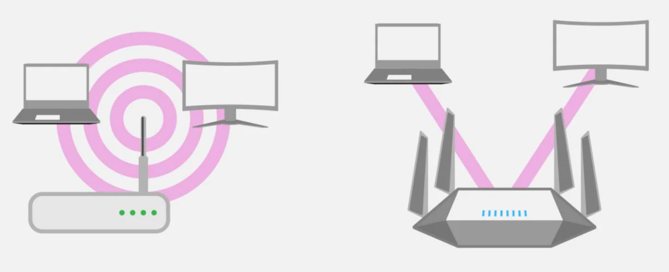
Beamforming is another technique to deliver higher throughput in wireless networks. To implement beamforming, the router identifies the location of the device requesting data and, instead of broadcasting the data in all directions, it transmits a more focused data stream directly at the requesting device (Figure 3). While beamforming is a relatively new requirement in cellular communications, especially in 5G, it’s been used in Wi-Fi networks for a number of technology generations.
Beamforming first appeared in Wi-Fi routers on an ad hoc basis with the introduction of 802.11n, also called Wi-Fi 4, which supports MIMO operation. MIMO is needed to implement beamforming. Since 802.11n does not specify how beamforming should be implemented, each vendor developed proprietary beamforming implementations. Those proprietary designs required the router and endpoint receiver cards to be from the same manufacturer. That requirement greatly limited the early adoption of beamforming technology. Things changed with the emergence of Wi-Fi 5.
Wi-Fi 5 (802.11ac) included the first set of specified beamforming techniques for Wi-Fi devices. Beamforming is not a requirement for Wi-Fi 5 routers, but it’s vendor-neutral and interoperable when included. Beamforming in Wi-Fi 5 is designed to help maximize the antenna resources on a router. To accomplish that, it adds support for multi-user MIMO (MU-MIMO), enabling a router to send signals to multiple endpoints simultaneously. Beamforming is necessary to support MU-MIMO. A directional signal is sent to each endpoint with beamforming, preventing signal interference between endpoints. The Wi-Fi 6 (802.11ax) standard increases the number of simultaneously supported MU-MIMO users, also made possible with beamforming.
Explicit vs. implicit beamforming
Explicit beamforming occurs when both the router and endpoint support Wi-Fi 5 or Wi-Fi 6. In that case, the communication begins with a ‘handshake’ that enables both devices to establish their respective locations and the channel used for data transmission.
For endpoints that support Wi-Fi 4 or older versions, a beamforming router may still attempt to target those devices, but without a handshake from the endpoint. This is called implicit beamforming or universal beamforming and works in theory with any Wi-Fi endpoint. Without the handshake, the router may not locate the endpoint as precisely.
The utility of implicit beamforming is limited, and many Wi-Fi 6 routers include it as a feature that can be turned on and off as needed. If the Wi-Fi network consists of mostly stationary endpoints, implicit beamforming may help improve performance. Devices such as tablet computers and mobile phones may experience dropped connections or degraded performance with implicit beamforming, and it may need to be turned off for best network performance.
Summary
While often considered a relatively short-range wireless technology, long-distance Wi-Fi transmissions up to 15 km are possible with the proper antenna selection. The importance of Wi-Fi antenna selection extends to multipath environments where two antennas can improve network reliability. Multiple antennas can be used in MIMO installations to improve Wi-Fi router performance. The implementation of explicit and implicit beamforming can further enhance the data transmission abilities of Wi-Fi networks.
References
Choosing the Right Wi-Fi Antenna for your Application, L-com
MulMultipathd Diversity, Cisco
The four types of directional Wi-Fi antennas and the maximum range of Wi-Fi signal, Siliceo
What is Wi-Fi 6?, Intel


Leave a Reply