As software and its associated memory footprint continue to expand in vehicles, automotive system designers need a deeper understanding of DRAM and its impact.
Robert Bielby • Micron Technology
 Today’s high-end vehicles are recognized as among the largest embedded software applications in the world, with a total memory footprint expected to grow from today’s staggering 100 million lines of code to over 300 million lines of code by 2030. Of course, the catalyst for this exponential growth is the move towards fully autonomous vehicles.
Whereas 10 years ago a more modest microcontroller might contain 50 million transistors, GPUs that can be found in today’s high-end cars can employ more than 25 billion transistors, an increase of 500X in a 10-year time frame. The increase in transistor count is also a good proxy for the overall increase in vehicular system-level complexity. And today, the automobile is widely considered to be one of the main drivers of many complex leading-edge products and technologies.
Automotive applications have pushed semiconductors into the functional safety arena. It is important to note that the first edition of the functional safety standard ISO 26262 published in 2011 was primarily limited to electrical and/or electronic systems with almost no consideration for semiconductors. However, since then, the focus has broadened to include the semiconductor industry — IC manufacturers, IP providers, and EDA companies. Eventually, with the second edition of the 26262:2018 specification came the addition of part 11 which is dedicated to semiconductors.
The ISO 26262 standard defines functional safety as the “absence of unreasonable risk due to hazards caused by malfunctioning behavior of electrical/electronic systems.”
Malfunctions are classified into two types of failures:
Systematic failures: These are failures that happen in a deterministic manner — typically introduced during product design or development. These failures are generally addressed by adopting well-documented processes and methodologies, including safety planning, safety concept documentation, requirements traceability, proactive safety analysis tools, robust verification, operational procedures, and other associated factors.
Random failures: These are failures that appear arbitrarily during the lifetime of a device. Random failures can be further divided into two categories: transient faults (single-event upsets or soft errors) or permanent faults (hard errors such as stuck at a logic level). These types of failures are generally addressed by introducing safety mechanisms that help identify the faults so the system can take actions such as correcting the fault or maneuvering to maintain a safe state.
Several safety mechanisms are employed at the memory hardware and system levels:
Redundancy — Typically implemented at the hardware level.
Cyclic redundancy check — Typically used for error detection.
Error correction code — Generally used for both error detection and correction.
Built-in-self-test — Takes the form of additional circuitry that verifies accurate device operation, either continuously or during power-up.
Various metrics measure the effectiveness of the safety mechanisms used to detect random failures in time (FIT) and the likelihood of risk. These metrics include single-point fault metric (SPFM) and latent fault metric (LFM), both used to measure the functional safety of a given hardware component.
ASILs
ASIL refers to the Automotive Safety Integrity Level. There are four ASIL levels defined by the ISO 26262 standard. ASIL A systems have the
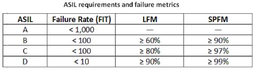
least stringent level of safety reduction, whereas ASIL D is the most stringent. Higher ASIL levels typically imply rising cost and complexity, thus the ASIL level required for a given system directly correlates to the severity, exposure and controllability of that system’s failure on the operation of the vehicle.
Memory and storage in the modern vehicle is expected to grow and total to more than 1 TB. Thus there is understandably an ever-increasing focus on the role of memory in achieving functional safety levels. The ISO 26262:2018 release had a focus on semiconductors. Specifically, Part 8, Clause 13 classifies a hardware element as either, basic, intermediate, or complex – a reference to the general complexity of a given semiconductor device or sensor.
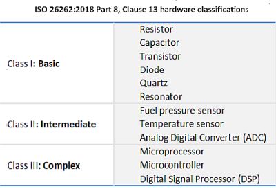
Historically, DRAM has been classified as a Class II – intermediate device, which belies the underlying complexity of DRAM. The underlying circuitry within a DRAM makes it apparent that DRAM would be more appropriately recognized in the Class III Complex range. The complexities include the following:
•Multiple states, operating modes, registers
•Many internal states/modes cannot be tested or analyzed without deep knowledge of implementation details and/or access to test modes
•Many failure modes cannot be identified, understood, and analyzed without knowledge of the design, implementation, and production process
•Safety mechanisms relevant for the safety concept are integrated
When designing automotive applications such as ADAS, system architects typically use commercial-off-the-shelf (COTS) devices, or automotive derivatives of these devices. There is a wide range of available auto-qualified COTS components including LPDDR4 and LPDDR5 DRAM.
Sometimes, designers may assume that legacy error-handling measures sufficiently address the end application. They don’t evaluate the effectiveness of these measures when used as safety mechanisms. Examples might include the use of in-line or sideband ECC on the host SoC – similar to its use in server or consumer applications.
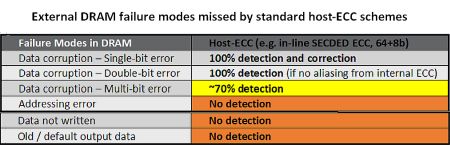
The rationale for this type of memory is that the host-ECC adequately covers the external DRAM. However, in the context of functional safety, and for some of the reasons described earlier (why DRAM should be considered a Class III hardware element), it becomes clear that standard host-ECC schemes do not perfectly cover all potential failure modes in the external DRAM. As such, diagnostic coverage of traditional host-based ECC solutions may be sufficient only for applications requiring up to ASIL B.
Because the automotive code footprint is expected to reach 300 million lines, a detailed understanding of DRAM operation is becoming necessary for achieving the requisite ASIL level. Detailed understanding and modeling of DRAM makes it clear that a classification as a Category II Hardware Element is over-simplistic.
To go beyond ASIL B, designers should specify a memory with systematic fault coverage addressed by an ISO 26262-certified process. Designers should also request data regarding any safety mechanisms that address such items as latent faults and multiple bit errors, as well as about other features that can help reach the ASIL target. Also recommended is that designers work closely with the memory supplier and the associated Functional Safety Office to design guidelines, associated random fault coverage features (as applicable) are employed for the desired ASIL level.
It’s important for system designers to keep in mind that memory by itself can’t be the whole safety solution for vehicles. Designers are ultimately responsible for building-in redundancies and safety mechanisms and for ensuring the holistic system design is safe and reliable.
References
Microchip Technology, “Functional Safety for an Expanding Set of Applications”
Microchip Technology, “Functional Safety Ready MCUs for Automotive Applications”


Leave a Reply