The Rexing V1 is a simple wedge-shaped dash camera that films in a 1080-line progressive scanning format. The lens is made of six glass layers and is fish-eyed to capture a 170° view of 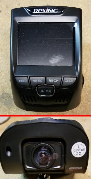 whatever it sees. There’s also a built-in vibration sensor, called a G-sensor in the promotional literature, that automatically locks any files recorded during a moment of unusual vibration. Like most dash cams, the VI records and saves video to a microSD card. But the V1 has a bigger capacity than most, supporting up to 128 gigabytes.
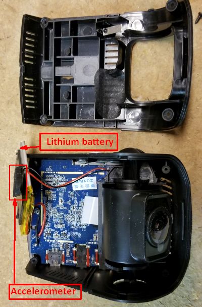
The V1 comes apart easily. Four ordinary Philips-head screws hold its two-piece plastic body together. Inside the camera body sits the camera image sensor, the main circuit board, and the lithium-ion battery.
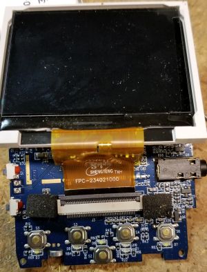
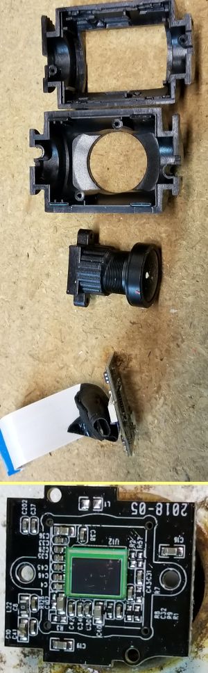
The image sensor sits in a small separate enclosure that rotates on a single axis. Two Philips-head screws attach the camera enclosure to the shaft on which it rotates. Once the shaft is off the cylindrical enclosure pops apart to reveal the image sensor. Once you get the enclosures apart, you can see that the main circuit board connects to the image sensor and to the liquid-crystal display through flat cables.
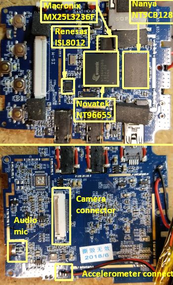
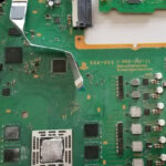
All the camera electronics other than the imaging sensor itself sit on a single circuit board. And a single chip handles all the imaging and control. The chip is a camera controller made by Novatek Microelectronics in Taiwan. It includes features such as a built-in hardware acceleration pipeline, auto white balance, and embedded video, audio, and JPEG codecs. The onboard processor is a MIPS32 device and there is a separate image processor.
Also on the main PCB is a 32-megabit CMOS serial NOR flash memory chip from Macronix, a DDR3 one gigabit static DRAM chip from Nanya Technology in California, and a synchronous buck regulator power supply chip from Renesas Electronics in Japan.
One thing you won’t find on any of the circuit boards is an accelerometer that would be necessary for the G sensor function. We found the accelerometer stuck to the lithium battery in a way that would probably let it move slightly in the dash cam enclosure if there was some kind of crash-like event. In that regard, you can view the lithium battery as perhaps doing double duty, providing power but also serving as a kind of pendulum mass to help the accelerometer detect anomalous events such as a crash.
An additional point to note is that the accelerometer is fairly large, as accelerometers in consumer devices go, so it’s probably designed to pick up relatively low vibration frequencies.
And speaking of the battery, it is a 320 milliamp-hour rechargeable lithium ion device. What’s notable is that several other dash cams now on the market use a supercapacitor instead of a lithium battery for power. The fact that the battery doubles as a pendulum mass for detecting crashes might help explain why Rexing chose to go with power from a battery rather than a supercapacitor, which probably would have been physically smaller.
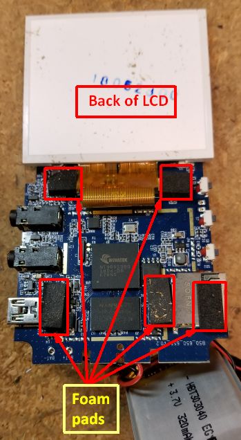
The final item we can comment on is the physical mounting arrangement of the circuit board in the enclosure. The main circuit board attaches to the enclosure with three Philips head screws, and you’d think that would be enough to hold the board firmly in any kind of normal use sitting on your car’s rearview mirror. But we also found five foam pads adhesively placed on the connection ports for the memory, power connection, GPS, and USB. They seem to be there for cushioning purposes, but you wonder why.
We have a couple theories. The simplest is that they help with the positioning and cradling of the liquid crystal display since they’re on the side of the PCB next to the LCD. But they might also be there to somehow help damp out innocuous vibrations that the G sensor might otherwise confuse with those arising from a crash. Of course, we’re only guessing.


Leave a Reply