The root complex in PCI Express (PCIe) is the intermediary between the system’s central processing unit (CPU), memory, and the PCIe switch fabric that includes one or more PCIe or PCI devices. It uses the link training and status state machine (LTSSM) to manage connected PCIe devices. The LTSSM detects, polls, configures, recovers, resets, and disables the devices as required during operation.
This FAQ looks at the basic functionality of the PCIe root complex and its interaction with other PCIe system components. We will also briefly consider multi-root PCIe architectures and close with a look at how redundant PCIe root architectures operate.
The PCIe root processes transaction requests received from the CPU and connects to devices on the PCIe bus. A root complex often contains more than one PCIe port; multiple PCIe endpoints, bridges, and switches can connect to the ports on the root complex or be cascaded throughout the system (Figure 1).
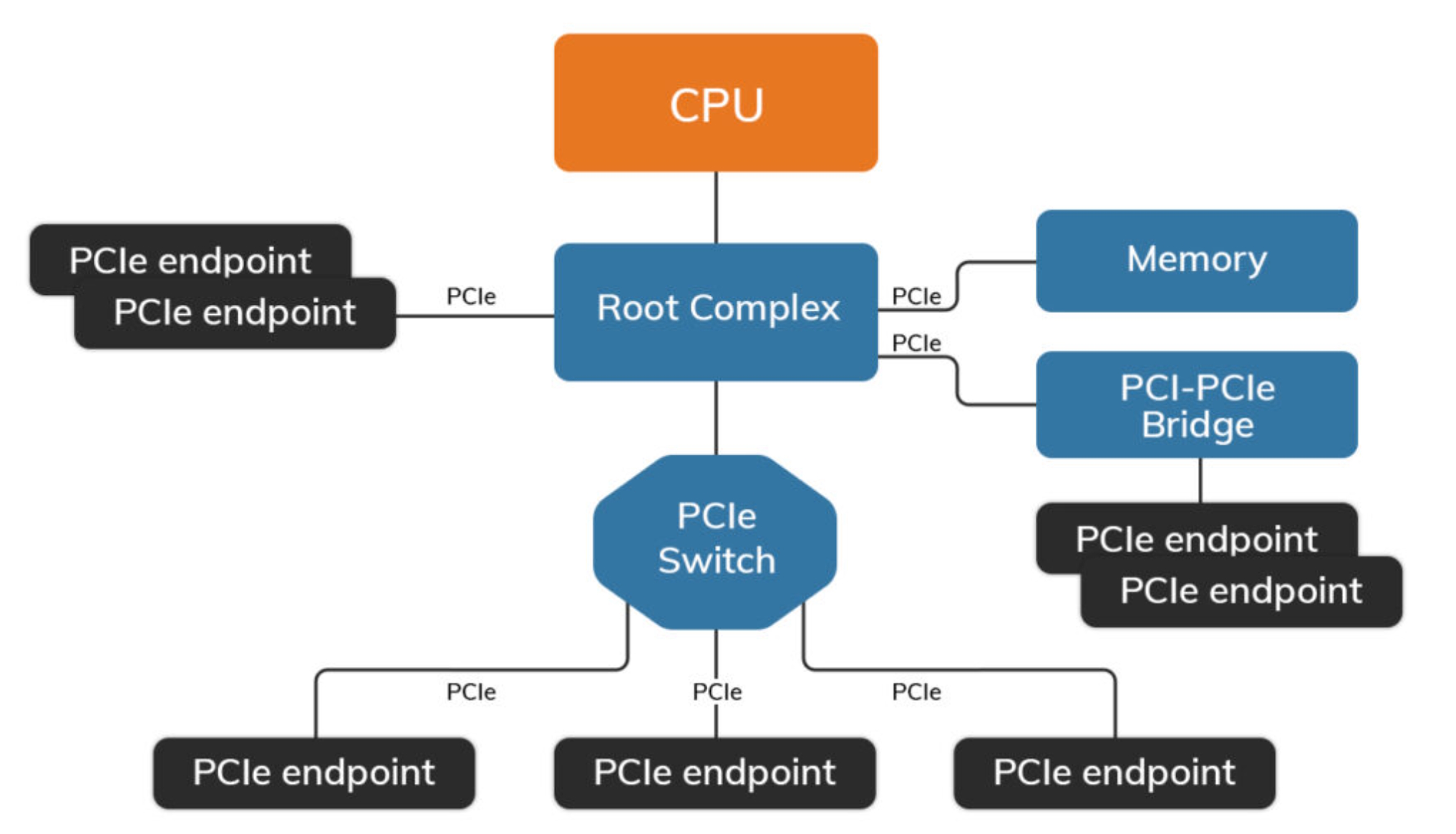
A master copy of a “Type 1 Configuration Table” is in the root complex and defines the host memory space accessible from each Endpoint device. Each Endpoint device holds the master copy of its own memory space in the host system as a “Type 0 Configuration Table.” Type 1 and Type 0 configuration tables are configured by the host operating system that controls the root complex. A PCIe bridge works as a tiered root complex with its own “Type 0 Configuration Table.” In addition to traditional applications, PCIe is being used as the main system interconnect technology in multi-host and embedded applications.
Multiroot architecture
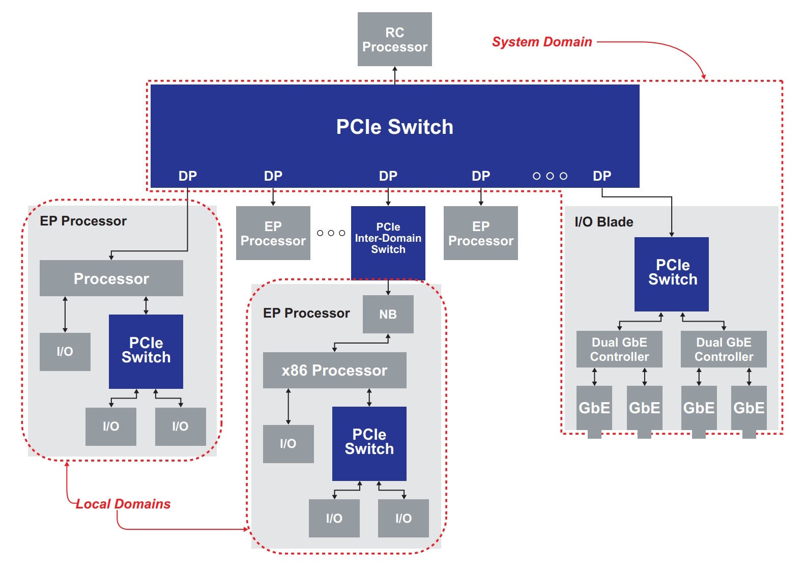
In a multi-host topology, the root complex at the top of the architecture is also the root complex for the system domain. For example, an I/O blade in the system domain can only be configured by the root complex in the system domain. Each local domain includes an endpoint processor (EP Processor) that acts as the root complex for its own domain (Figure 2).
Redundancy
Another form of multi-root architecture is a dual-root topology that has an active and standby root complex to support high availability and redundancy. During normal operation, the active root complex is employed and connected to the active port of a PCIe interconnect switch, and the interconnect switch isolates the standby root complex from the system. Real-time monitoring of heartbeat and checkpoint messages are regularly sent to the standby root complex by the active root complex. If the standby root complex detects a failure in the primary root complex, the interconnect switch is directed to perform a switchover, after which the standby root complex takes over control.
In high-availability systems, a managed switchover between the primary and backup root complexes can be user-initiated for performing maintenance, software upgrades, system testing, and other functions. In addition, the active root complex can be required to reset a watchdog timer on a regular basis. If the timer is not reset, the standby root complex takes over system operation. The use of a watchdog timer can serve as a backup method of system monitoring in addition to heartbeat and checkpoint messaging.
Summary
In a basic PCIe system, the root complex connects the CPU and memory to the PCIe switch fabric, including one or more PCIe or PCI devices like endpoints, switches, or bridges. In a multi-host topology, each local domain includes an endpoint processor that acts as the root complex for its own domain. Redundant designs with active and standby root complexes can be implemented to support high-availability systems.
References
Introduction to PCIe, Prodigy Technovations
Root Complex, Wikipedia
Using PCI Express as the Primary System Interconnect in Multiroot Compute, Storage, Communications and Embedded Systems, Renesas
Related content
What is PCIe gen 6 and how do I test it? Part 1
What is PCIe gen 6 and how do I test it? Part 2
Leave a Reply