
The Peripheral Component Interconnect Express (PCIe) is a high-speed serial computer expansion bus standard. It’s the common motherboard interface in systems from personal computers to servers and storage devices and is used with graphics cards, sound cards, hard disk drive host adapters, SSDs, Wi-Fi, and Ethernet hardware connections. It uses a three-layer protocol stack to deliver high-speed and reliable data transfers.
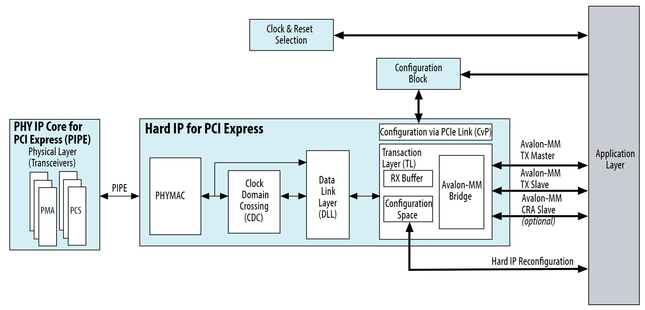
This FAQ provides a high-level overview of the protocol’s components, their functions, and how they work in unison. The three layers (Figure 1) are:
- The Transaction Layer (TL) connects the bus to the Application Layer and includes the Configuration Space, which manages communication, the RX and TX channels, the RX buffer, and flow-control credits. The transaction layer receives 32-bit words called double words (DWs) called transaction layer packets (TPLs) on the 32-bit interface from the device.
- The Data Link Layer (DLL) maintains data integrity and manages the transmission and reception of data-link layer packets (DLLPs). It generates cyclical redundancy code (CRC) values for transmissions and checks CRC during reception. It manages retry operations and initializes the flow control for DLLPs.
- The Physical Layer (PHY) controls the speed, lane widths and lane numbering. It also performs clock recovery from the received data and uses CRC to help correct data errors.
Data structure and flow
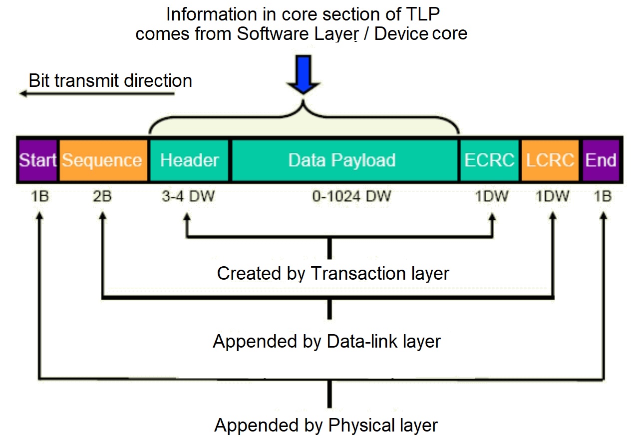
The TL receives data from the application layer and the data builds up as it passes through the other layers in the stack (Figure 2). The transaction-layer packets (TPLs) received from the application layer include a header, data payload, and an optional end-to-end CRC (ECRC) that’s generated by the application logic. The DLL handles link management and adds a sequence number and a link CRC (LCRC). When the DL receives a packet, it sends an ACK (success) or NACK (failure) to the sender, which retransmits the data in the case of a NACK. The physical layer consists of two differential pairs and uses 8b/10b encoding that maps 8-bit words to 10-bit symbols to achieve DC balance. It also performs clock recovery and adds framing information.
Flow control
PCIe uses a point-to-point credit policy for managing buffers. The DLL sends packets that indicate the amount of receiver buffer space available in units called credits. The transmitter must ensure that the buffer space is not exceeded.
The TL uses virtual channels (VC) and traffic classes (TC) to prioritize data transport. VCs are used for differential bandwidth allocation and have dedicated physical resources, including buffering, flow-control management, and so on. The TC is required by the packet header, and it determines the relative priority of a given transaction. The maximum data payload (MDP) in a PCIe system is a system-wide user-defined parameter. Transmitters are not allowed to send packets that exceed the set MDP value.
PCIe transactions
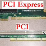
Four types of transactions originate in the TL: memory, input/output (I/O), configuration, and message. Memory transactions are used for transferring data. I/O transactions provide backward compatibility with the PCI protocol, the predecessor to PCIe. Configuration transactions are used by the root complex to configure the system when it’s turned on. message transactions interrupts, error conditions, and other information.
Transactions are further classified as posted, non-posted, and completed:
- Posted transactions don’t send a completed TLP sent to the requester. Messages and memory writes are examples of posted transactions.
- Non-posted transactions are ones where the requester expects to receive a completion TLP from the device completing the request. Memory reads I/O reads and writes, and configuration reads and writes are examples of non-posted transactions.
- A completion transaction is initiated by the destination when read data is available.
Summary
This FAQ has reviewed PCIe data structure and flow, flow control, and transaction types. The PCIe stack consists of the TL, DLL, and PHY layers. The DLL and PHY both use CRC for error correction.
References
Introduction to PCIe, Prodigy Technovations
PCI Express Protocol Stack, Intel
PCIe Primer, Verien Design Group
Related content
What is PCIe gen 6 and how do I test it? Part 1
What is PCIe gen 6 and how do I test it? Part 2
Leave a Reply