
There are many different materials and methods for creating PCB materials. The electronics used in numerous applications benefits from the large number of options for PCBs. Hobbyists often choose the least expensive PCB, however, it’s essential to choose appropriate PCB materials when prototyping is done, and high-volume product development and manufacturing become the focus. Applications that use high-speed signals, digital or analog, are the most likely to benefit from a detailed consideration of PCB materials such as the roughness of copper traces and uniform fiber weaves and resin that have dielectric constants that are as similar as possible. Detailed considerations of PCB materials for high-frequency signals improves signal integrity.
What concerns should you have about the PCB for your application?
The materials used for the PCB matter if the application requires anything from rugged construction for harsh environments such as outer space to extreme flexibility in a PCB for a wearable electronics device. High-frequency signals and circuits are especially more complicated to design; therefore, PCB material selection is more critical with high-speed circuit designs. Applications that typically need high-performance PCBs include routers, servers, power amplifiers, transceiver modules, and any high-speed data channels (e.g., PCIe 4.0 and higher.)
The type of signals in the circuit on the PCB may greatly benefit the circuit’s operation based on how the PCB is constructed, as well, not just how the circuit is designed. There are a number of other options in creating a PCB that affect circuit operation and performance, including rough or smooth copper traces, dielectric constants, materials that might need to be resistant to specific environments such as humidity, skin effects, the ability of the PCB to withstand physical stress, and the number of layers in the PCB that affect size and cost. Other PCB considerations might be the ease of production, form factor, and system integration requirements.
Materials: Rigid to flexible and everything in between
PCB technology has not only improved but has enabled new applications. Early prototypes that are used to test the circuit design are a step above breadboarding the circuit. Circuit design can be simulated but modeling a circuit is never as detailed as building the circuit, so every possible parameter is in play. Modeling and simulating circuits is only as good as the number of parameter data programmed into each component model. After simulating circuit operation, the circuit might be implemented on a bread-board or as a prototype on a cheap, rigid PCB. The PCB materials for the prototype may be lower cost because bugs need to be worked out on the circuit design and tests will reveal performance issues in the worst case.
Improving the PCB materials will improve performance. Therefore a prototype using the best materials for the intended application is built and tested. For example, a PCB that will be launched into space will need to be robust, hardened against radiation, and made of materials that reduce potential problems. Another application, such as a wearable temperature-monitoring wireless communicating device, would have extremely flexible PCB with very different materials. For example, the Blue Spark TempTraq is a wearable thermometer patch that sends temperatures at regular intervals to a smartphone. According to Blue Spark, “Printed electronics is the term used for a relatively new technology that defines the printing of electronic circuits and components on common media such as paper, plastic, and textile, using standard graphic arts printing processes and press equipment. But instead of using standard inks, newly developed electronic inks are used to print active devices, such as thin film transistors and thin printed batteries. Although the concept of printed electronics has been around for some time, recent advances in conductive ink chemistry and flexible substrates promise to deliver a flood of new markets and applications.”[i]

The application affects the type of PCB that’s needed. For example, in the case of a microcontroller (MCU) board that’s used for training and/or development, a rigid PCB is suitable as training and development boards are frequently exposed to mechanical stress and vibrations when plugging or unplugging connectors and jumper wires. A rigid PCB can withstand multiple insertion and withdrawal connections, whereas a flexible PCB offers different benefits like the TempTraq thermometer patch or other disposable or wearable devices.
Wearable biosensors, for example, can be developed on extremely flexible PCBs so that the circuit can withstand both folding and mechanical stress as they are worn on the skin.[ii] The robustness, high performance, and life of an electronic product depend upon the PCB that’s used.
In other applications, the size and value of the product don’t matter as much as whether the product is reliable and offers a remarkable user experience. User experience can be enhanced if the product is strong enough to withstand accidental falls or vibrations. For instance, a television remote is often dropped, but the ideal PCB material for this type of application holds together and doesn’t fall apart. Similarly, other digital electronic products such as microwaves and Automatic Teller Machines (ATMs) are frequently used and often by multiple users. Nevertheless, these sturdy devices function efficiently over a long lifetime. Buttons can fail after millions of times getting pressed. A PCB can malfunction due to excessive temperatures. Overall, the careful selection of PCB materials can avert flaws, making the product more robust. [iii]
How many layers for your PCB?
Single-sided PCB
Single-sided PCBs are printed with a conductive layer on only one side. They are the most common type of PCB, and in use since the 1950s. Single-sided PCBs are still used in both commercial and academic projects because they are both easy to use and cheap. Single-sided PCBs are often still used in power supplies, LED lighting, vending machines, and industrial relays. [iv]
Double-sided PCB
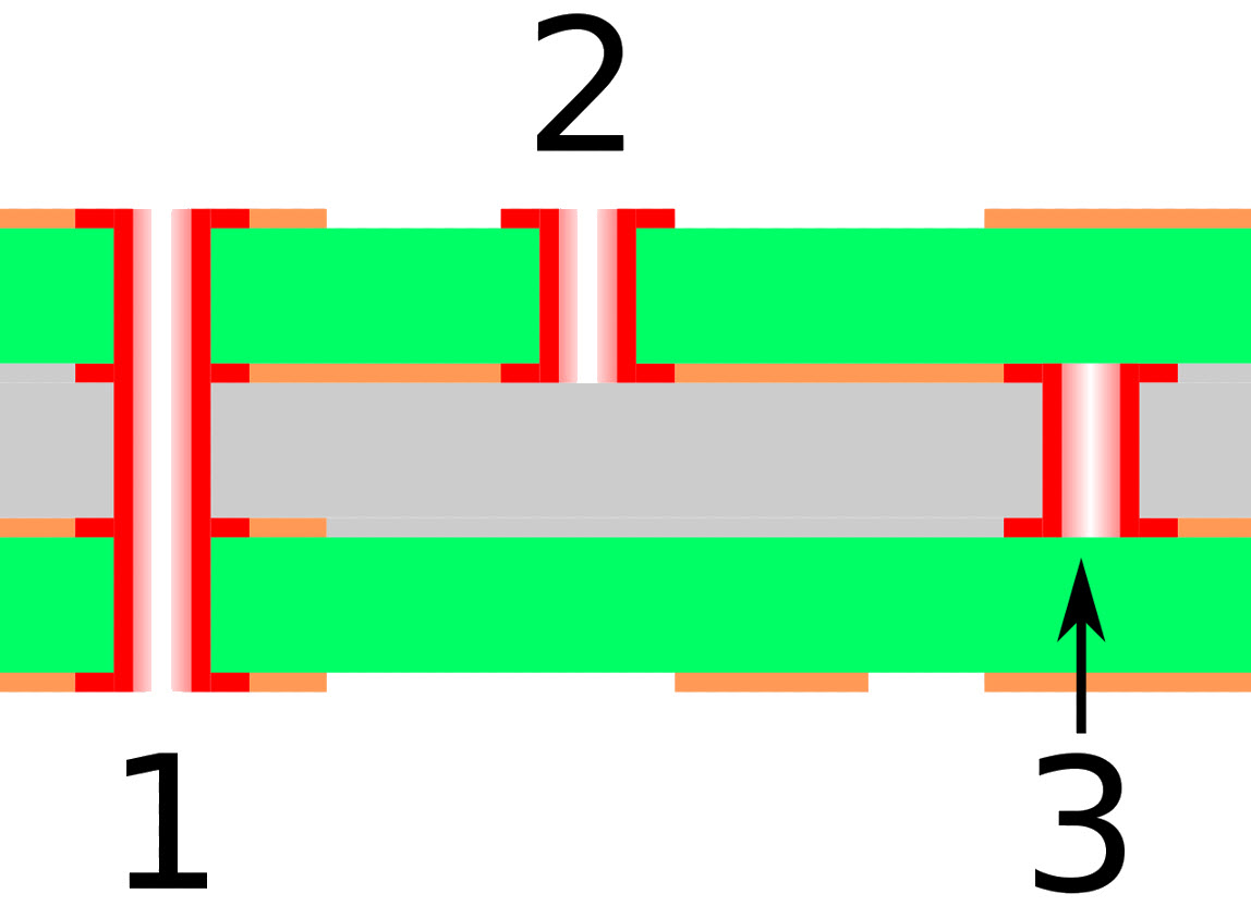
Double-sided PCBs offer a more enhanced platform for circuit development. Both the top and bottom layer are used for routing signals, which reduces the board’s overall size. Reducing board size can reduce the cost of a product, especially if the PCB requires an enclosure. The PCB’s layers are connected using vias. A via is a hole that electrically connects a node (e.g., a pad) from the top to the bottom side of the PCB.
Double-sided PCBs are considered to be the most popular type of PCBs. Examples of some primary applications that commonly use double-sided PCBs are converters, industrial controls, traffic systems, and control relays. [v]
Multilayer PCB
Multilayer PCBs contain three or more sets of conductive and dielectric layers. The PCB’s conductive layers are separated by a dielectric layer. Layers can be interconnected using vias. Multilayer PCBs can accommodate a considerable network of traces within a limited area, which can reduce both the cost and overall size of the end product. Multilayer PCBs are used in computers, GPS technology, atomic accelerators, fiber optic receptors, space probe equipment, and many other products.[vi]
Different types of PCB materials and their uses
Aluminum PCB
The base core of the PCB consists of aluminum, which enables a high level of thermal dissipation by the PCB. The overall performance and durability products are enhanced as the circuitry cools down efficiently. Aluminum PCBs are environmentally friendly since the aluminum is recyclable. The mechanical strength is also remarkable as compared to its total weight. An aluminum PCB benefits both high power and thermally sensitive circuits. [vii]
Flexible PCB
As the name suggests, flexible PCBs are flexible, and they can be folded or bent to some extent. They are made from plastic materials such as polyimide, which adds elastic properties to the PCB.[viii] Flexible PCBs establish electrical circuits while efficiently managing mechanical challenges. They are widely used in medical, military, and industrial applications. [ix]
Rigid PCB
Rigid PCBs are the most common type of PCBs in use. They are cheaper than other types of PCBs. Rigid PCBs are inflexible, and their shape cannot be changed, unlike flexible PCBs. A computer motherboard is a typical example of rigid PCB. [x]
Rigid-flex PCB
Rigid-flex PCBs are a combination of rigid and flexible PCBs. The combination enables the development of mechanically challenging designs. Rigid-flex PCBs can replace an older, more traditional combination of rigid PCBs, connectors, and cables. As the mechanical connections are reduced, the overall efficiency of electrical contacts is enhanced, and the flexible part protects the circuit from mechanical hazards. [xi]
Rigid-flex PCBs are used in military, aerospace, medical, telecommunication, automotive, and industrial applications. [xii]
This just scratches the surface of the available choices in PCBS beyond available options in layers.
Next: Part II, which type of Printed Circuit Board (PCB) materials would be worth investing in to improve signal integrity?
[i] https://www.bluesparktechnologies.com/index.php/industry-solutions/about-printed-electronics
[ii] https://www.molex.com/molex/products/family?key=medical_wearables&channel=products&pageTitle=Introduction
[iii] https://www.pcbcart.com/pcb-capability/pcb-materials.html
[iv] https://www.amitroncorp.com/printed-circuit-boards/single-sided.html
[v] https://www.amitroncorp.com/printed-circuit-boards/double-sided.html
[vi] https://www.amitroncorp.com/printed-circuit-boards/multilayer.html
[vii] https://www.pcbway.com/pcb_prototype/General_introduction_of_Aluminum_PCB.html
[viii] http://www.pcbuniverse.com/pcbu-flex-pcb.php
[ix] https://pfcflex.com/applications/
[x] https://www.theengineeringprojects.com/2018/04/rigid-pcb.html
[xi] https://www.cicor.com/products-services/printed-circuit-boards/rigid-flexible/
[xii] http://www.rigiflex.com/faq/rigid-flex-pcbs-applications
Leave a Reply